

1. Introduction
2. Methodology
2.1. Numerical model
2.2. Experimental setup
3. Results and Analysis
3.1. Fuel volume flow rate effect
3.2. Momentum flux ratio effect
3.3. Oxidizer/Fuel ratio effect
4. Conclusion
기 호 설 명
MFR : Momentum flux ratio
MW : Molecular weight
U : Axial velocity
Q : Volume flow rate
R : Specific gas constant
T : Temperature
α : Spreading angle
ρ : Density
1. Introduction
The staged combustion cycle has been widely employed in development of rocket engine because it can reduce system loss, increase efficiency and provide higher performance and more thrust[1]. During its development process, high frequency combustion instability observed for high pressure and temperature condition is always a major issue. It is a phenomenon that pressure oscillations are coupled with heat release, and excessive heat transfer is generated as they oscillate in the chamber[2-5]. Lots of previous studies show that the injector is one of key elements and has great impact on combustion instability [6,7]. And, gas-centered swirl coaxial (GCSC) injector is used typically in a liquid rocket engine adopting staged combustion cycle[8-10].
In our previous work, the GCSC injector with kerosene fuel was studied in various aspects. In order to analyze the combustion instability of the GCSC injector with a subscale chamber, a scaling method was established by keeping hydrodynamics similarity[11]. Based on this, analysis of fuel-oxidizer mixing and combustion was presented by Kim. et al. with a gas-gas injection in GCSC injector[12]. And, also the spray patterns and injection characteristics were investigated[13]. One of the most significant results in our previous research is that the kerosene model condition was established based on actual rocket engine conditions by simulating gas-liquid injection of GCSC injector with gas-gas injection[11,12].
In the present study, the fuel is replaced by methane because experiments can be carried out relatively easily and detailed chemical mechanism for methane is available for the numerical simulation. And, our goal is still to study stability of injector with a combustor. However, before we analyze combustion instability of GCSC injectors with methane, flow and combustion characteristics should be investigated first. Because if flow or flame is unstable, there is a great possibility that combustion instability will occur.
Three important factors of GCSC injectors are studied numerically and experimentally. They are fuel volume flow rate (Qf), momentum flux ratio (MFR), and oxidizer/ fuel (O/F) ratio. The momentum flux ratio is defined as the ratio of oxidizer momentum flux to fuel momentum flux and it is a key parameter controlling fluid flow induced by the GCSC injector. It is formulated in the following section.
2. Methodology
2.1. Numerical model
The geometry and mesh grids of the model chamber with a single GCSC injector is shown in Fig. 1. The model is the same as that in our previous study[12]. Oxidizer in a gas phase is injected axially through the center, whereas fuel is injected tangentially through 8 holes located on A-A and B-B cross sections of the injector. After injection, fuel and oxidizer will be mixed in the recess part with a length of 8 mm. Injector and combustor lengths are 117.2 mm and 393 mm, respectively. In the present study, hybrid mesh grids are adopted and the grid number is about 530,000.
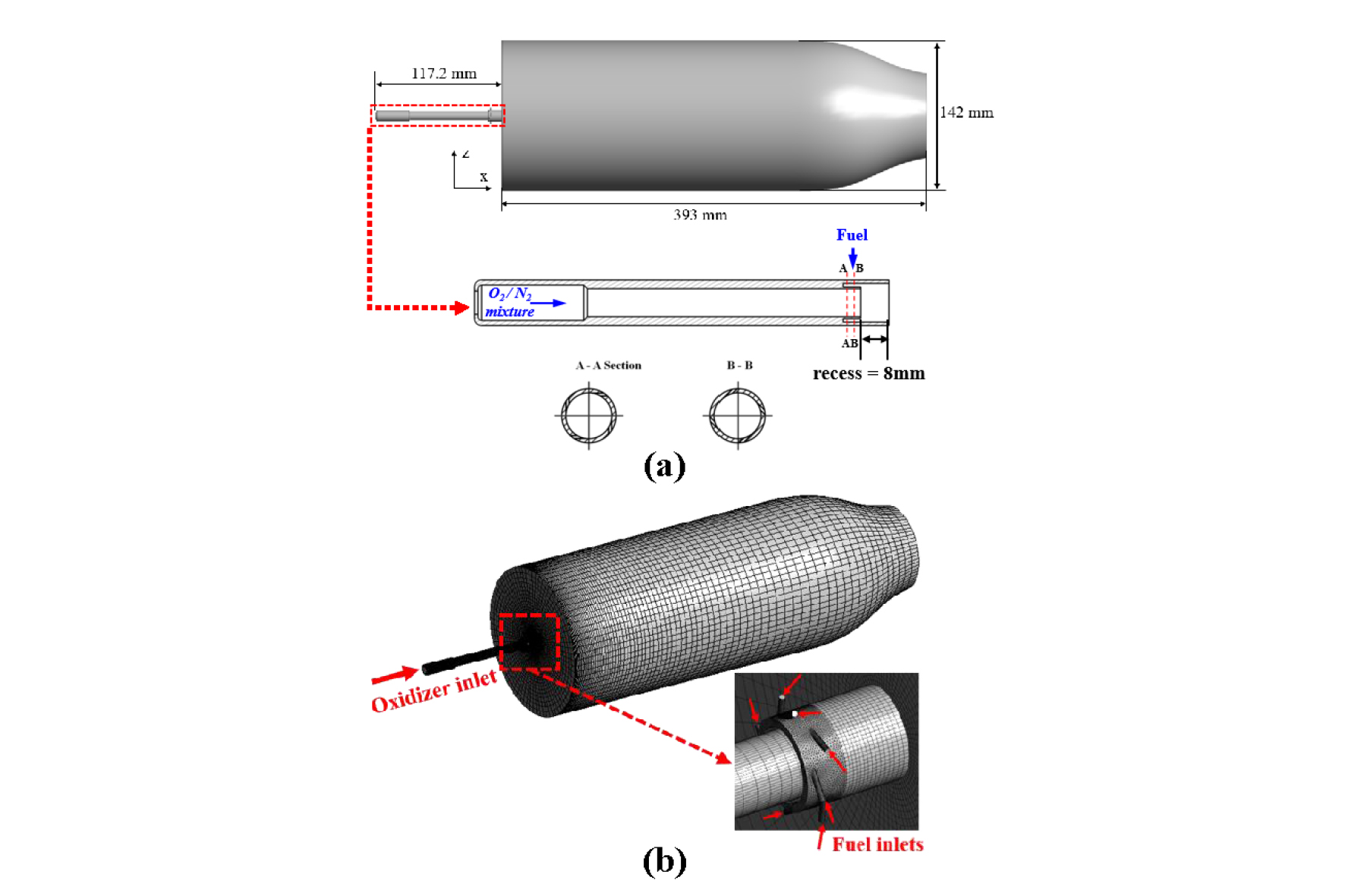
In this study, oxidizer is a mixture of oxygen and nitrogen and fuel is methane. In the actual rocket engine, oxidizer is oxygen with gas phase and fuel is kerosene with liquid phase. However, the operating pressure and temperature usually exceed the critical pressure and temperature when fuel and oxidizer are injected into the chamber. That means the process of interaction between fuel and oxidizer inside the injector approaches a gas-gas interacting scheme, not a gas-liquid scheme[12]. When the propellant of rocket engine is gasified, the essential features of gas-liquid flow interaction should be maintained by keeping the hydrodynamic similarity between gas-gas injection and gas- liquid injection. Detail explanation about similarity rules can be found in the literature[13]. In this study, a key parameter controlling fluid flow induced by the GCSC injector is momentum flow ratio (MFR) as describe in Kim et al.‘s works[11-13]. The MFR is defined as
| $$MFR=\frac{\rho_oU_o^2}{\rho_fU_f^2},$$ | (1) |
where the subscript, o and f, indicate oxidizer and fuel, respectively. And ρ and U are density and axial velocity.
The method to keep the hydrodynamic similarity and simulate actual liquid fuel/ gaseous oxidizer with gaseous fuel/ gaseous oxidizer was developed to be a scaling method in our previous study[11,12]. By adopting the scaling method, the gas kerosene/ gas oxygen model condition is calculated. Based on the kerosene model condition, methane model condition is calculated in the present study.
As aforementioned, effects of three factors are studied and flow inlet conditions are summarized in Table 1. The kerosene model condition calculated in our previous study is used for a comparative study with methane fuel[12]. We would like to set the same MFR of kerosene cases as the present methane cases. However there is a problem that fuel and oxidizer volume flow rate are variable with a fixed MFR. First of all, we select the fixed MFR for actual operating condition and change fuel volume flow rate (Qf) to analyze its effect on GCSC injector with methane fuel. By comparing two results with each other, a suitable Qf can be determined. Then, studies with various MFR and fixed Qf are conducted to check MFR effect on flame shape and combustion. Finally, in order to analyze O/F ratio effects, conditions with various O/F ratio and with MFR, Qo, and Qf fixed, are established. A reasonable O/F ratio is determined for future numerical simulations and experiments after the analysis of O/F ratio effects. Detailed conditions for three factors will be shown in the later section.
Table 1. Boundary conditions for three considered factors
The governing equations for the simulation in the present study are as follows:
continuity equation,
| $$\frac{\partial\rho}{\partial t}+\nabla\cdot\;(\rho\overrightarrow v)=0,$$ | (2) |
momentum equation,
energy equation,
species equation,
| $$\frac\partial{\partial t}(\rho Y_i)+\nabla\cdot\:(\rho\overrightarrow vY_i)=-\nabla\cdot\;{\overrightarrow J}_i+R_i$$ | (5) |
and finally, equation of state,
| $$\rho=\frac p{(R/MW)T}$$ | (6) |
In order to simulate the turbulent flow, Reynolds-averaged Navier-Stokes (RANS) equations based on k-ε equations are solved by the commercial CFD solver. Methane GRI 3.0 mechanism is adopted and steady diffusion flamelet model is adopted[14,15].
2.2. Experimental setup
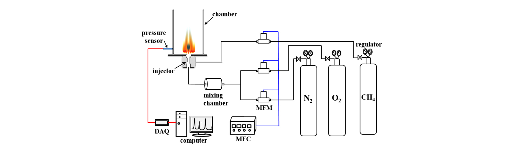
Fig. 2 shows the diagram of the experimental setup. Fuel and oxidizer are supplied and controlled by MFC. PCB sensor is installed at the chamber wall to detect pressure fluctuation. In this study, experiments are mainly used to capture flame patterns and to compare flame shape with numerical results.
3. Results and Analysis
3.1. Fuel volume flow rate effect
The methane model condition is calculated based on actual real operating condition by keeping the similar MFR. Since MFR is a ratio between oxidizer and fuel momentum, for a fixed MFR, there will be various combination of fuel and oxidizer volume flow rates. After the fuel is changed to methane, a suitable fuel volume flow rate should be defined. Consequently, the fuel volume flow rate becomes the first factor to be considered. The MFR for the kerosene model condition is set as the baseline value and four different fuel volume flow rates are selected to observe the effect on flow and combustion with the single GCSC injector. The flow conditions are shown in Table 2. The MFR is kept as a similar value to kerosene operating condition. Qf is increased with the oxidizer flow rate.
Table 2. Flow conditions for numerical study on Qfeffects
| Kerosene | CH4 (Case1) | CH4 (Case2) | CH4 (Case3) | CH4 (Case4) | |
| Qo (LPM) | 328.7 | 111.8 | 62.5 | 41.1 | 20.7 |
| Qf(LPM) | 27.0 | 27.0 | 15.0 | 10.0 | 5.0 |
| MFR | 12.2 | 12.8 | 12.9 | 12.6 | 12.8 |
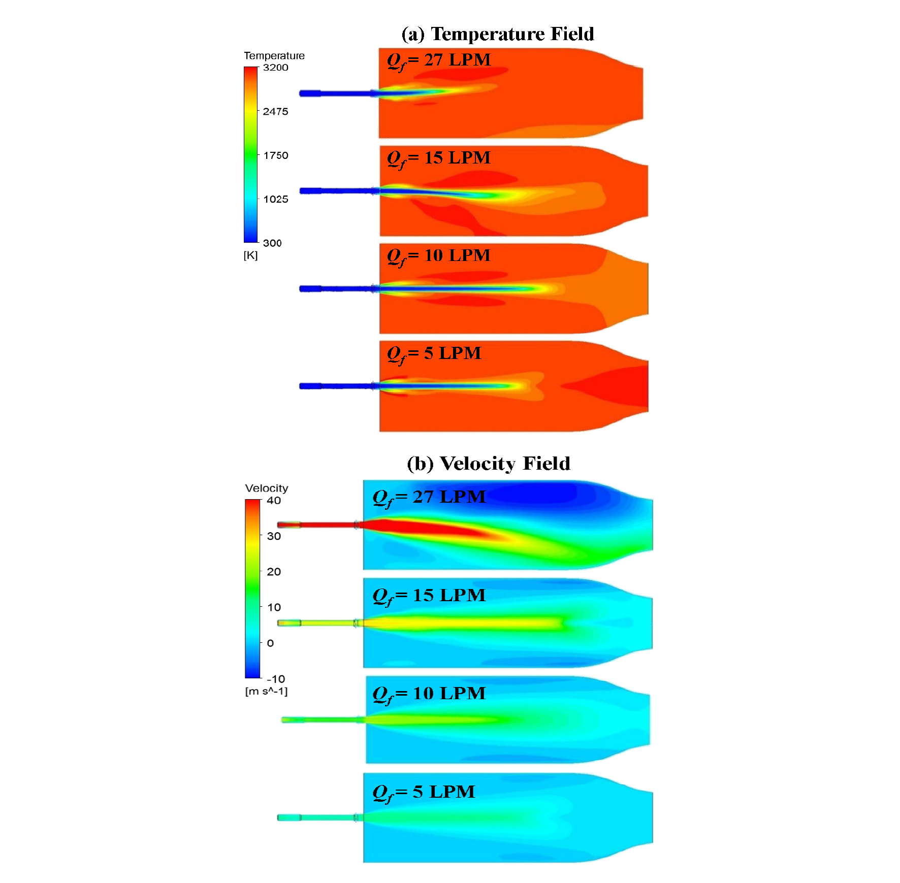
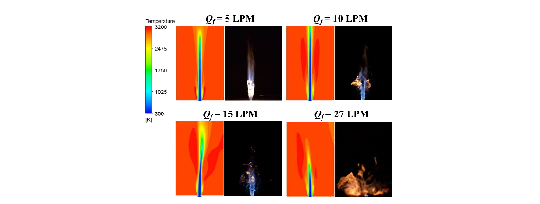
Results of numerical simulation with four different Qf are compared and shown in Fig. 3. When Qf equals to 27 LPM, which is the same as the Qf for Kerosene operating condition, the flame shows asymmetric shape as seen in temperature fields. Similarly, with Qf of 15 LPM, flame is not symmetric. When Qf is reduced to 10 and 5 LPM, flame becomes symmetric and has stable shape. The fact that flows with larger Qf show asymmetry can be also found in velocity fields as shown in Fig. 3(b). Next, in Fig. 4, numerical results are compared with experimental results for various Qf. As in numerical results, larger Qf also show asymmetry in experimental results. It is because tangential momentum caused by fuel injection larger than axial momentum from oxidizer injection. The large difference between tangential and axial momentum induces the asymmetric flow, resulting in unstable flame. With Qf of 27 LPM, the axial momentum is too small to form the center flame. Only tangential flame with yellow color can be seen in the figure. When Qfreduces to 15 LPM, the axial center jet flame can be seen but tangential flame still is asymmetric. In the case of 10 LPM, tangential flamebecomes symmetric and stable because tangential momentum decreases. And, the center jet also shows relative stable flow compared with that of larger Qf. When Qf decreases further to 5 LPM, central jet flame appears because tangential momentum is too small with little fuel injection. From these flame patterns, 10 LPM is the suitable Qf and will be adopted in the following simulation and experiments.
3.2. Momentum flux ratio effect
After the fuel volume flow rate Qf is determined, effect of momentum flux ratio (MFR) is investigated. When the Qf is fixed at 10 LPM, the MFR can be changed by increasing oxidizer volume flow rate. As shown in Table 3, nine cases with increased MFR are selected and the MFRs for methane are the almost same as those for kerosene in our previous study[12]. The MFR of Test No. 4 is 12.6 which is same as the operating condition in the actual engine. Calculated temperature fields are compared with experimental flame shapes and results in four cases are shown in Fig. 5 with the ascending order of MFR. From the results, we can see that the tangential flame is getting smaller as MFR decreases. In order to quantify this phenomenon, we introduce the parameter of spreading angle characterizing the injection characteristics of GCSC injectors[13]. The spreading angle is calculated by using the Eq. 7,
| $$\alpha=\tan^{-1}\left(\frac{Tangential\;Velocity}{Axial\;Velocity}\right)$$ | (7) |
Table 3. Flow conditions of MFR effects
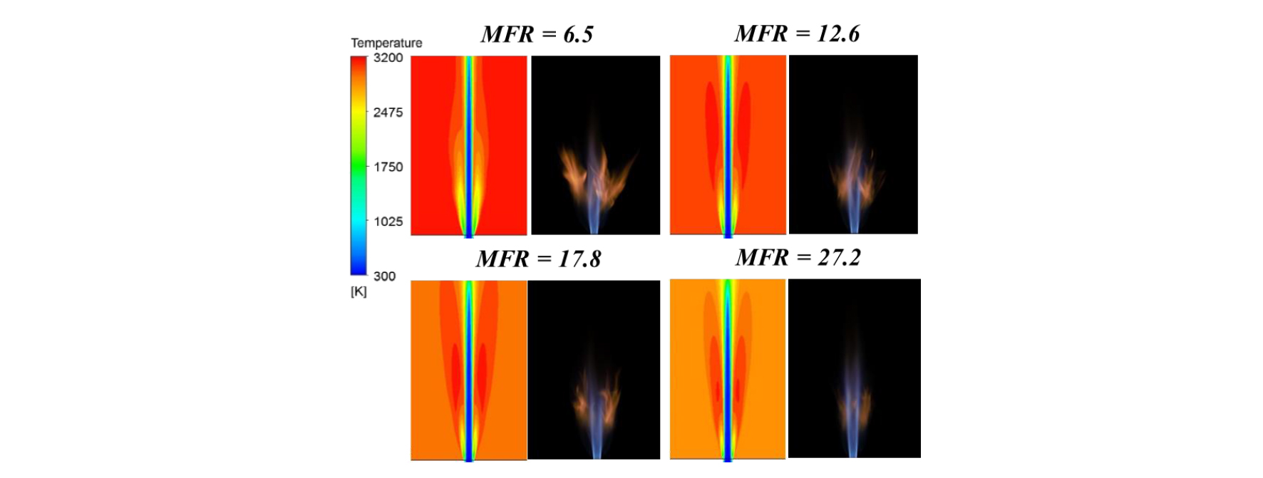
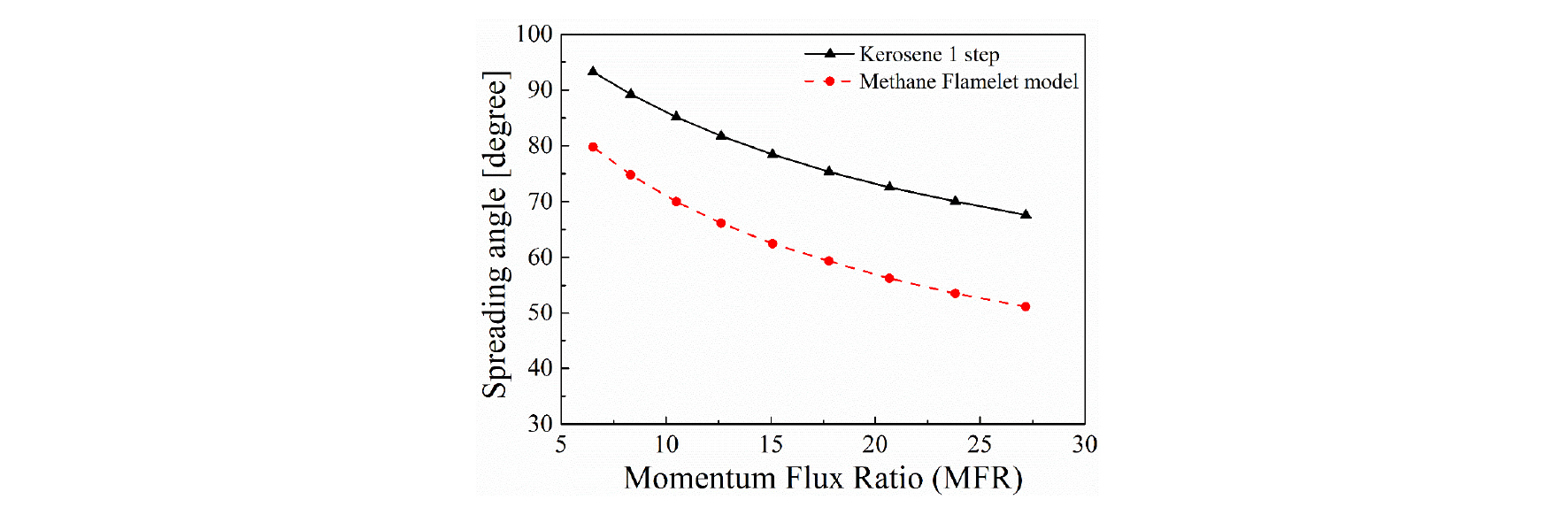
In Fig. 6, the spreading angle of methane fuel is compared with that of kerosene in the previous work. Firstly, the spreading angle of 9 cases decreases as MFR increases. The spreading angle is calculated by numerical results. Although spreading angle cannot be measured with experimental results, the decreasing trend of spreading angle with MFR is confirmed by experimental results as shown in Fig. 5. Spreading angles from both numerical and experimental results show the same qualitative tendancy. Secondly, the error in spreading angle between two fuels is about 17.7%. This is an interesting point to be considered when we determine the flow conditions of GCSC injectors. Because we still need to generate similar flow and combustion pattern to actual condition with any fuels. In order to make spreading angles of methane close to that of kerosene we considered the third factor affecting flame shape and flow in next section.
3.3. Oxidizer/Fuel ratio effect
The third parameter is oxidizer/fuel ratio (O/F ratio). As aforementioned, the spreading angle between kerosene and methane fuels showed large errors. By comparing the flow condition of kerosene with methane, we found that the O/F ratio is different even if we adopt the same MFR. Obviously, MFR is an important factor. But when the oxidizer and fuel volume flow rate is changed to adjust MFR, the O/F ratio also should be considered.
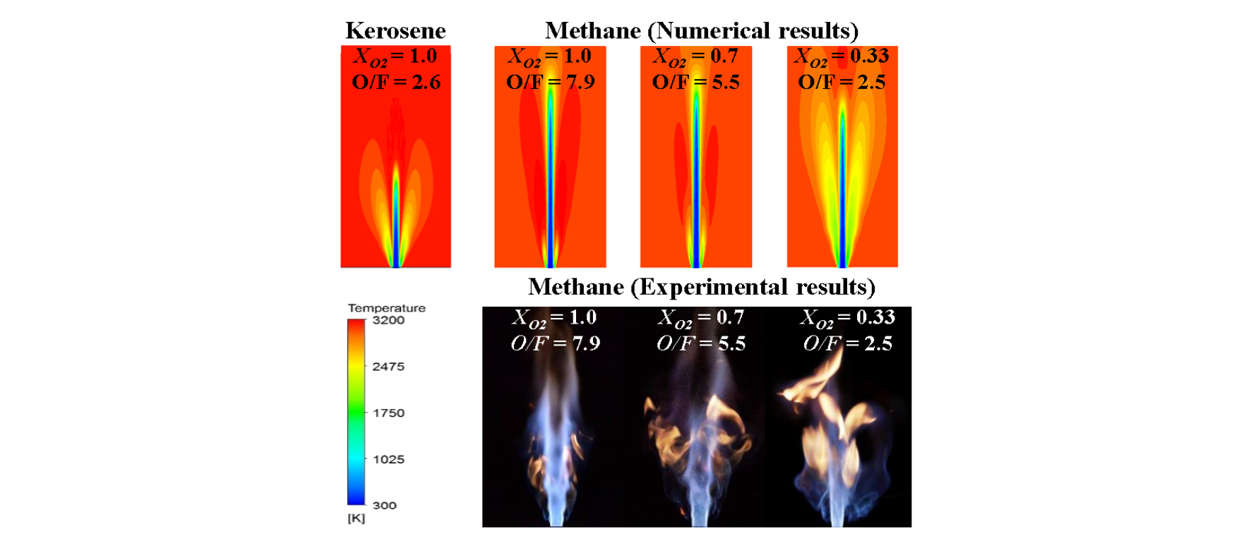
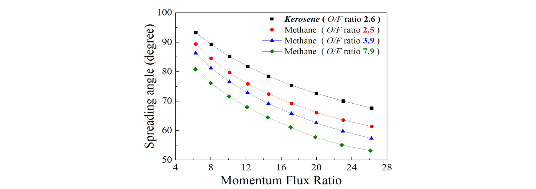
The method to change O/F ratio is to adjust oxygen and nitrogen mole fraction in oxidizer while the Qf, Qo, and MFR are kept constant. Flow conditions are shown in Table 4. Three different O/F ratios of 2.5, 5.5 and 7.9 are selected for comparison. The O/F ratio 2.5 is similar to that of kerosene. In Fig. 7, flame pattern of kerosene with O/F ratio of 2.6 and MFR of 12.2 is shown as a baseline. From the numerical and experimental results, it can be seen that tangential flame appears as O/F ratio decreases with MFR fixed in three cases. When the O/F ratio of methane has the value 2.5, which is similar to that of kerosene, the spreading angle also becomes similar to each other. As shown In Fig. 8, all of the spreading angle decrease with MFR increases, which agrees with the tendency found in effect of MFR. As O/F ratio decreases, the spreading angle of methane increases and is getting close to kerosene. Consequently, the O/F ratio with a value of 2.5 will be adopted in our future simulation and experiments.
Table 4. Boundary conditions of O/F ratio effects
4. Conclusion
Three factors affecting flow and combustion induced by the GCSC injector have been investigated in this study. From the study on Qf effect, a suitable Qf was determined for simulation and experiments. And then, the MFR effect have been observed with methane and compared with that of kerosene. The spreading angle decreases with MFR. Finally, in order to get more reasonable flow and combustion fields, the O/F ratio effect shoul be considered additionally. A suitable O/F ratio was found here and would be applied for our future numerical simulations and experiments with a simulant fuel of methane.
In our future works, the model chamber with single/ multi injectors will be adopted to analyze and predict combustion instability.
